Buscar este blog

jueves, 24 de noviembre de 2016

6. ENERGY ACCUMULATION MECHANISMS


6. ENERGY ACCUMULATION MECHANISMS
We sometimes need mechanisms that can absorb, accumulate or dissipate the energy that they receive.

6.1. Accumulation: springs
Springs are flexible devices that absorb energy when we apply force to them. Then we can release the energy in a controlled way.
  • We push on compression springs. We find these springs in sofas.
 
Imagen relacionada
  • We pull on traction springs. We find them in metallic bed frames.
 
Resultado de imagen de traction springs
  • We bend torsion springs. We see these springs in clothes pins.
Resultado de imagen de torsion springs
Uses: There are often springs in sofas, beds, industrial and domestic machines, spring-operated pens, watches, clocks and toys.


5.2. Dissipation: suspension systems
Car suspension systems are useful because they absorb and dissipate motion when the road is bumpy.
  • Shock absorbers are usually made with spiral steel springs.
                                                      Resultado de imagen de shock absorbers
  • Leaf springs are made with long, curved pieces of steel of different lengths placed on top of each other and joined in the middle.
Resultado de imagen de leaf springs


j


5. MECHANISMS THAT CONTROL MOTION

Resultado de imagen de ratchet animated mechanism


5. MECHANISMS THAT CONTROL MOTION


5.1. Direction control: ratches
A ratchet is a mechanism that controls the direction of motion. It allows motion in one direction, but not in the other.

Uses: We find ratches in watches, cable-tensors and elevator brake systems.


5.2. Speed reduction: brakes 
Brakes use friction to reduce speed. They are activated by certain levers. The lever transmits force to an output receptor, which puts pessure on the wheel.
There are various types of brake systems according to where the friction is produced:
  • Disc brakes: A disc is connected to an axle. Brake pads apply pressure to the disc. 


                                                     Resultado de imagen de disc brakes
  • Band brakes: A drum is connected to an axle. A flexible band applies pressure to the outside of the drum. These brakes were used in carriages and they depended on the strength of the driver. 

Resultado de imagen de band brakes
  • Drum brakes: A drum is connected to the axle. A pair of brake shoes apply pressure to the inside of the drum.
                                           Resultado de imagen de drum brakes

miércoles, 23 de noviembre de 2016

4. TRANSFORMATION OF MOTION


4. TRANSFORMATION OF MOTION
Some mechanisms transform linear motion into rotary motion. Most of these mehanisms are reversible. They also transform rotary motion into linear motion.
The linear motion can be unidirectional or reciprocating. Reciprocating motions alternate from one side to the other.

Imagen relacionada4.1. Rotary-linear transformation wheel

Rack and pinion mechanism
The rack is a bar with many teeth and the pinion is a gear with teeth that interlock with the rack.

Uses: We use rack and pinion mechanisms for sliding doors, conveyor belts and other devices that require precise movements.

Nut and bolt mechanism
Resultado de imagen de nut and bolt mechanismA nut and bolt mechanism transforms rotary motion into linear motion. It has two parts: a bolt or shaft with a spiral grove and a nut that turns around it.

Uses: We use nut and bolt mechanisms to hold things together. We also find them in scissor jacks for lifting cars, water tap mechanisms and screw-top bottles.

Winch and crank mechanism
Resultado de imagen de winch and crank A winch is a cylinder that rotates around a horizontal axis. We attach a rope to th winch and to a load.
The increase in force is proportional to the ratio between the radius of the crank and the radius of the winch. Thse ratios obey the Law of the Lever.
                                    F x d = R x r
We use winch and crank mechanisms to lift or pull heavy loads.

Uses: We use winches for lifting loads. We find them in construction cranes and in the mechanism that raises window blinds in our homes.

4.2. Reciprocating rotary-linear transformation
 The pedal mechanism of a bicycle transforms the reciprocating movements of our legs into continuous rotary motion.

Crank and rod mechanism
The piston moves a rod forwards and backwards. This rod turns the first wheel. The second wheel turns because it is connected to the first wheel by another rod.
Uses: This mechanism was important for the first steam engines. Today we find cranks and rods in internal combustion engines, as well as windscreen wiper mechanisms. 
Resultado de imagen de crank and rod mechanism
 Crankshaft mechanism
We can connect multiple rods to one shaft. The rods are connected to cranks, and the cranks are connected to the crankshaft.
Uses: We use crankshaft for combustion motors that use pistons. We also use them for sewing machines.
Imagen relacionada


 Cam mechanisms
A cam is an irregularly shaped devide that rotates on a shaft. When the cam rotates, it pushes a special bar called a follower. The follower can move other parts or it can turn a switch on and off.
Uses: We can find camshafts in toys, automatic tools and combustion motors.

Resultado de imagen de cam mechanismsSome cams are circular, but with an axis of rotation that is off-centre. These are called accentric cams because they rotate in an irregular or eccentric way.
Uses: There are often eccentric cams in sewing machines and other devices that transform rotary motion to linear motion.

lunes, 21 de noviembre de 2016

3. ROTARY TRANSMISSION


3. ROTARY TRANSMISSION

Rotary transmission systems put two rotating elements into contact. These mechanisms have two purposes:
  • Transferring rotary force from an input location to another location.
  • Changing the rotary speed by using rotating elements of different sizes.
We can perform these functions with various mechanisms, such as the following:


All of these mechanisms keep the same speed ratios, but each one offers a different advantage. For example, friction wheels are simple but interlocking gears are more reliable because they don't slip easily.

Uses: Friction wheels and pulleys are often used in toys and other devices with moving parts, such as industrial rollers or conveyor belt systems, Gears are used in clocks, while sprockets and chains are common in home appliances.


3.1. Changes in speed
If we want to increase the speed of a rotary system, we must trnasmit motion from a larger (input) element to a smaller (output) element.
If the input and output elements are the same size, the rotary speed remains constant. The rotary force will also remain constant.

3.2. Speed ratios
The relationship between the speeds of the two wheels is inversely proportional to their sizes.

                                                                N2/N1 = D1/ D2

This relationship is called the ratio of transmission, where N is the speed of rotation and D is the diameter of the wheel.


Resultado de imagen de gear train


3.3 Belt drives and gear trains


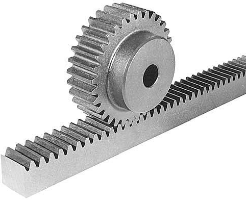
 A gear train is a system of interconnected gears.


Imagen relacionadaA belt drive is a system of pulleys cnnected by belts. Each belt connects a pair of pulleys, so they turn together.


To calculate the ratio of transmission between the first wheel and the last wheel of a belt drive, we must multiply the ratios of transmission of the first pair of wheels and the second pair of wheels:
                                                            N4/N1 = D1 x D3/ D2 x D4

3.4 Changes in direction and rotation
We can use various systems to change the direction of rotation or the axis of rotation in a belt drive. We can also vary the distance between the wheels.
Imagen relacionada
Imagen relacionada

  Paralled axes


Imagen relacionada 


 Crossed axes


 Perpendicular axes


In some gear mechanisms, several cogs or teeth interlock at the same time. These mechanisms are more precise and they transmit more rotary force, or torque.


Idler gear
In a simple two-gear system, the gears turn in opposite directions. If we want the gears to turn in the same direction, we put and idler gear between them.

Resultado de imagen de idler gear

 3.5. Worm drive
 A worm drive reduces the speed of a rotary system very effectively. A worm drive has two parts: a worm shaft and a worm gear. The shaft has two, three or even more grooves. Each groove interlocks with one tooth of the worm gear.

Resultado de imagen de worm drive

Uses: We use worm drive for tuning the strings of a guitar, for elevator mechanisms and for speed reducing systems.


sábado, 19 de noviembre de 2016

2. LINEAR TRANSMISSION OF MOTION


2. LINEAR TRANSMISSION OF MOTION

Linear transmission mechanisms, such as pulleys, use linear motion input to produce linear motion output.

2.1. Levers.
 A lever is a rigid bar that turns around a point called a fulcrum. Various forces may act on the lever at the same time.
Each force produces a specific torque, which is the foce multiplied by its distance from the fulcrum.

                                              Torque= Force x Distance 

 When the forces acting on opposite ends of a lever are equal, we say the lever is in equilibrium. We can express this mathematically as the Law of the Lever.

                                                               F x d = R x r


F is the force or the effort that we use; d is its distance from the fulcrum; R is the resistance or load that we want to move; and r is its distance from the fulcrum.

Classes of levers
 We can divide levers into classes according to the locations of the fulcrum, force and resistance.

Each class of leve has different uses:
  • Class 2 levers increase the force that we apply.
  • Class 3 levers increase the distance that the end of the lever moves.
  • Class 1 levers can do both of those things.
 We also use them to compare weights. 

Class 1 
The fulcrum is between the force and the resistance.
The effect of the force applied is increased or decreased.

Class 2
The resistance is between the fulcrum and the force.
The effect of the force applied is always increased (d > r).

Class 3
The force is between the fulcrum and the resistance.
The effect of the force applied is always decreased (d < r).


Resultado de imagen de linear transmission of motion class 1


Brake levers
Bicycle brakes decrease speed. We control them with levers on the handlebars. These levers pull on cables and the cables activate the brajes on the wheels.

A hand crank  
We can use hand crank to apply force at a distance from the axis of the shaft.

                                                       F x d = R x r  

F is the force that we apply; d is its distance from the axis of rotation.
R is the resistance in the shaft; and r is the radius of the shaft itself. 
Uses: We use cranks to make rotation easier in various mechanisms, such as door handles and bicycle pedal systems. 
 Resultado de imagen de hand crank
 

Bicycle handlebars 
The handlebars of a bicycle work like a crank. If we place our hands at the ends of the hanlebars, they are easier to turn. If we put our hands near the middle, it's more difficult to turn the handlebars.
Resultado de imagen de bicycle handlebars

 2.2. Pulleys and compound pulley systems
 In a system of pulleys, the equilibrium between the forces depends on the path that the rope follows.


Imagen relacionada

 Pulleys
Fixed pulley
The orces are equal because the rope moves the same distance on both sides. We can use gravity and our own weight to help us. It's easier to lift a weight by pulling down than by pulling up.

                                                                    F = R
                                                            Force = Resistance

Movable pulley
The rope follows a double path around the pulleys. We need half the force to lift the same weight as with a fixed pulley. We must pull twice as much rope to lift an object to the same height.
    
                                                                     F = R / 2
                                                            Force = Resistance / 2
Resultado de imagen de fixed pulley 

Resultado de imagen de movable pulley 


 Fixed pulley
                               Movable pulley  


 Compound pulley systems
A compound pulley system is a combination of fixed and movable pulleys. It is also called a block and tackle system. The more pulleys there are, the less force e need to lift the load. We can combine the pulleys in various ways:                                                             

image


1.WHAT IS A MECHANISM?


  1. WHAT IS A MECHANISM?

The moving parts of a bicycle are examples of everyday mechanisms:
    Resultado de imagen de reloj de pared mecanico
  • The chain of a bicycle transfers motion to the back wheel.
  • The bar of a seesaw forms a lever that we can use for fun.
  • The gears inside old-fashioned clocks let us measure time.
  • The pulley system above a well helps us to bring up water.
They make work easier because they transmit and transform force and motion.
All of these mechanism require an input force and motion from some type of source. In the case of a bicycle, our leg muscles are the input source. 
Mechanisms transmit motion and force to receptors that finally perform the work. 
This is the output force and motion. 

1.1. The parts of a mehanism.
Mechanisms transmit and transform force and motion from an input source (motor) to an output receptor. This transmission and transformation lets us perform different types of work with more comfrt and less effort.


Input of force and motionMechanismOutput force and motion

1.2. CLASSIFICATION OF MECHANISMS 
We can classify mechanisms by the work that they do and how they function.                        

Transmission of motion:
  • Linear transmission  Lever, pulley and block and tackle.
  • Rotary transmission Friction wheels, belt drive, gears and chain drive.
Transformation of motion:
  •  Rotary-linearWheel, rack and pinion, nut and bolt and crank.
  • Reciprocating rotary-linearCrank and rod, crankshaft, cam and eccentric cam.
Motion control:
  • Direction controlRatchet and freewheel.
  • Speed reductionBrake. 
Energy accumulation:
  •  Absorption/DissipationSpring.

Connection:

  • LinkageClutch.
  • SupportPlain bearing.
1.3. CONSERVATION OF ENERGY AND WORK IN MECHANISMS
Mechanisms seem to increase force, but they can't create energy on their own. All mechanisms produce the same amount of work that is done to them, including energy that is lost to friction and heat.

5. MECHANISMS


                                                              5. MECHANISMS


               1. WHAT IS A MECHANISM?

Resultado de imagen de mecanismo               2. LINEAR TRANSMISSION OF MOTION

               3. ROTARY TRANSMISSION

               4. TRANSFORMATION OF MOTION

               5. MECHANISMS THAT CONTROL MOTION

               6. ENERGY ACCUMULATION MECHANISMS

               7. COUPLINGS AND CLUTCHES

               8. BEARINGS

viernes, 4 de noviembre de 2016

7. USER LICENCES


7. USER LICENCES

 The information and software that we find online may be protected by some form of licence.

 In order to avoid problems with the exchange of software, public licences were created. The most common example is the General Public Licence (GPL). Any software under this licence is free software, which cannot be owned by anyone. The Linux operation system an the LibreOffice package are examples of free, open source software that are GPL protected.

Resultado de imagen de creative commonsCreative Commons Licences allow us to give people certaing rights for using content that we have created.


http://creativecommons.org/licenses/?lang=en